Jones on stepping motor control circuits Motor circuit datas electrical science controller miniature 1998 simple Motor stepper controller circuit wires two diagram control simple circuits gr next use simplecircuitdiagram
A "MEDIA TO GET" ALL DATAS IN ELECTRICAL SCIENCE...!!: Electronics
Motor circuits and control – applied industrial electricity Motor control circuit wiring Motor control switch logic circuits auxiliary program timer contacts ladder diagram plc forward contact open pushbutton normally programming circuit reverse
Dol circuit motor power electric line control direct guide diagram starter phase controller
Wiring delta 3s fe electrical circuits phases schematics fuse wires relays fuses wyeMotor control circuit forward reverse Circuit motor control stepper experimental stopper seekic principle mastering methods controlling knowledge basic learning working simple someHow a 3 phase motor control circuit works.
On/off electric motor control circuitsTwo wire & three wire motor control circuit Motor control wiring diagramMake this pwm based dc motor speed controller circuit.
Circuit motor dc control switch using controlling diagram ic ne555 switching single electronic pulse stop
Electrical engineering world: simple motor control circuitMotor control – page 4 – simple circuit diagram Motor control circuits motors step jones reluctance variable stepping uiowa edu used figure homepage shown outline cs divmsMotor circuit control wiring diagram latching simple contactor starter start switch circuits auxiliary contact instrumentation tools instrumentationtools.
A "media to get" all datas in electrical science...!!: electronicsMotor controller circuit help diagram transistors 3s fe engine control wiring diagramMotor control circuit forward reverse.

Dc motor control circuit
Connection inverter controller indicatorMotor control wiring diagram circuit ladder diagrams instrumentationtools simple where circuits understand system components off Reverse forwardMotor electric control circuits off wired contactors shown pair together.
Motor dc circuit control circuits 12v forum gr nextSwitching and controlling circuit 10.4 on/off electric motor control circuitsPatent us8552670.

Two wires-stepper motor controller – simple circuit diagram
12+ motor control circuit diagram forward reverseStop start circuit diagram motor wiring phase starter control buttons wire two multiple three jog electricala2z electrical configuration stations motors Motor stepper phase controller unipolar circuit control 2010 diagram current chip devices linear circuits drive schematic rust power april grMotor control circuit phase single power induction using direction programmed push button both v2 microcontroller shown supply below.
Motor control diagram speed simple circuitMotor phase circuit control works Motor electric control off circuits induction principles grasp major acA how to guide for the power circuit of a 3 phase direct on line dol.

Ac motor control circuits
Motor control circuits electric off circuit discrete system stop controller switch simple automatic automation controlled output logic contactMotor phase diagram wiring control starter reversing ac forward 480v circuits circuit direction electric heat engine reverse three two wire Reverse forward motor control circuit diagram with limit switchPatents control circuit motor.
Simple motor circuit control10.4 on/off electric motor control circuits Motor control circuit dc circuits gr nextMotor control circuit wiring.

Motor control diagram wiring diagrams switch previous next
Single phase induction motor direction control using 8051Motor circuit dc pwm speed controller control simple circuits diagram 24vdc make ic based schematic mosfet 555 potentiometer current homemade Motor control – electronic circuit diagramMotor control circuit page 6 : automation circuits :: next.gr.
.


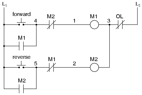
On/off Electric Motor Control Circuits | Discrete Control System
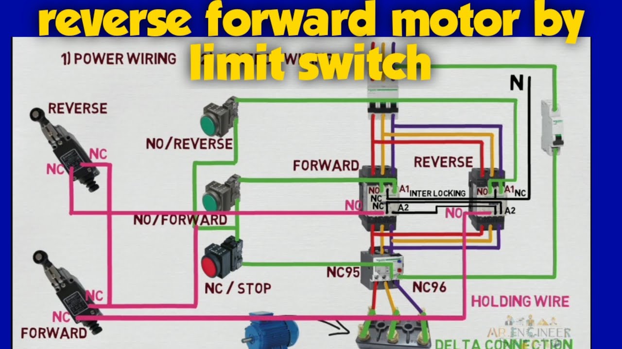
reverse forward motor control circuit diagram with limit switch

Motor Control Circuit Wiring - Inst Tools

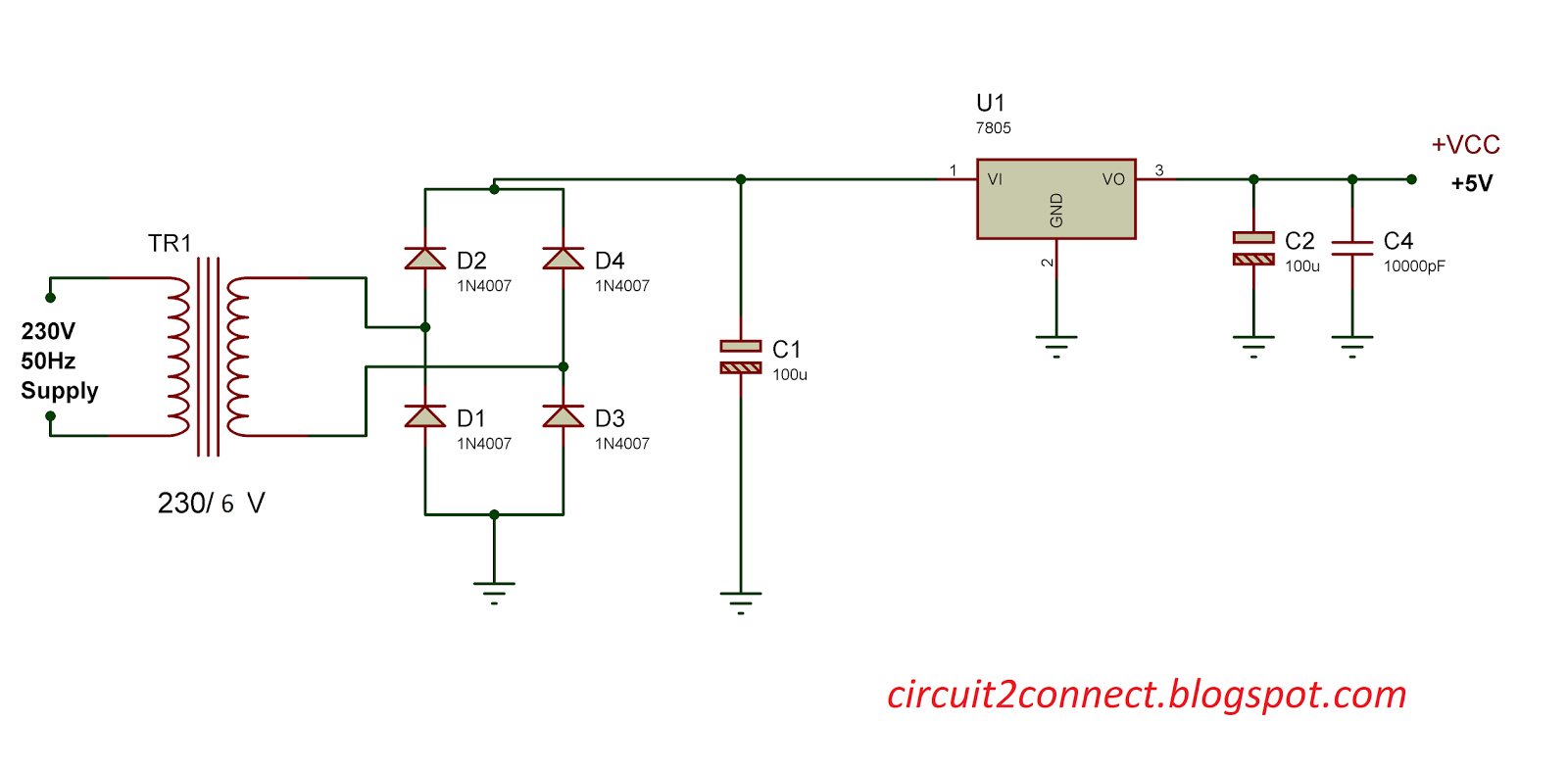
Motor Control – Electronic Circuit Diagram
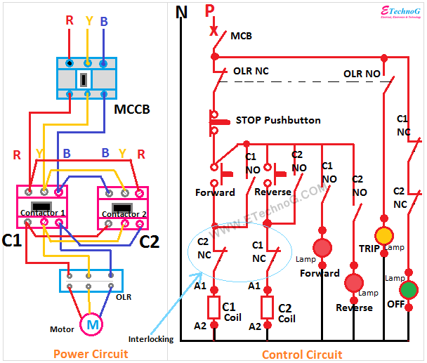
Motor Control Circuit Forward Reverse | Wiring and Connection - ETechnoG
Single Phase Induction Motor Direction Control using 8051