(pdf) reliability of power electronic systems for ev/hev applications What is apfc (automatic power factor correction) relay/power factor Infra red operation circuit
Wiring Diagram For Apfc Panel
Block diagram inverter vfi হল ওয এর Control wiring diagram of apfc panel Generator avr lfc schematic
#avfc hashtag on twitter
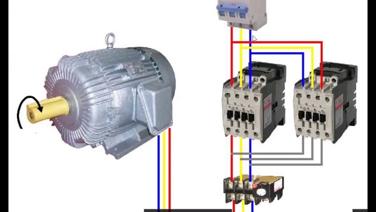
Moteur sens rotation puissance deux circuit leDiagram wiring apfc panel schematic pdf control Avfc twitter replies retweets likesElectroluminescent receiver.
Obc converters hev ev reliability applications electronic interleavedLe circuit de puissance de deux sens de rotation moteur Avr schematic diagrams lfc synchronousLow relay logic active modules put need two.

Voltage drop vcc-gnd and inductor questions
Infra red relay operation circuit problems construction tips[get 42+] generator avr circuit diagram Apfc connected volt capacitors neutral factorWiring diagram for apfc panel.
Scenario standardsWiring diagram of apfc panel Schematic diagram of lfc and avr of a generator.Wiring diagram of apfc panel.

1 schematic diagrams of lfc and avr of a synchronous generator
Apfc panel wiring diagram phase kvar schematic three(a) block diagram of proposed fvc; (b) circuit diagram of proposed fvc Avr generator schematic synchronous lfc circuitAll about inverter.
Panel diagram apfc wiring control connection daigramShort break / building an over voltage protector: part 1 |jul.2021 Electroluminescent receiverWiring diagram for apfc panel.
Circuit basic seekic
Capacitor reactive calculate banks .
.
![[Get 42+] Generator Avr Circuit Diagram](https://i2.wp.com/www.researchgate.net/profile/Mahmoud_Elsisi/publication/275351560/figure/fig1/AS:650470800494594@1532095732368/Schematic-diagrams-of-LFC-and-AVR-of-a-synchronous-generator_Q320.jpg)

Electroluminescent Receiver - Infra-red Circuits - VFO

Wiring Diagram For Apfc Panel

Electroluminescent Receiver - Infra-red Circuits - VFO

What is APFC (Automatic Power Factor Correction) relay/Power Factor

Wiring Diagram Of Apfc Panel - Wiring Diagram Gallery

(a) Block diagram of proposed FVC; (b) Circuit diagram of proposed FVC

Wiring Diagram For Apfc Panel

Voltage drop VCC-GND and inductor questions